NorthSec 2026 Badge
During the closing ceremony, it was announced that this year’s badge featured 3 tracks and 10 challenges. I have very little experience with electronics, so this is a very beginner-friendly write-up! I may not have all the terminology correct, so please feel free to let me know (:
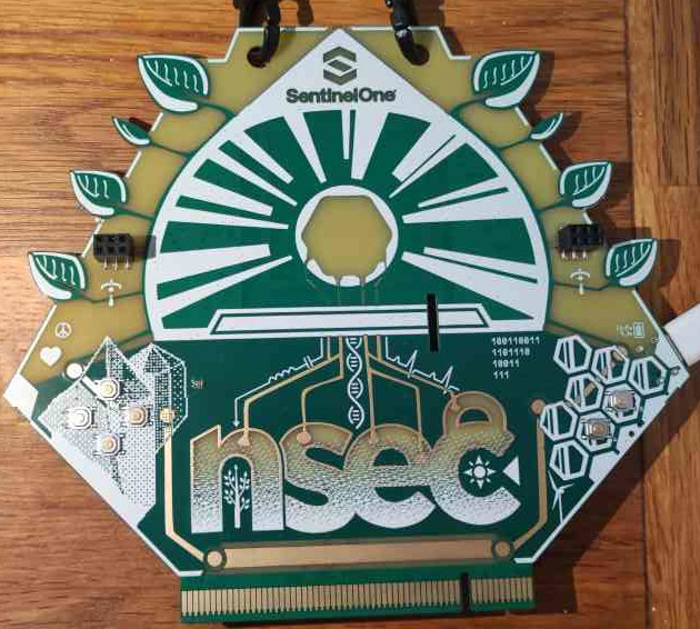
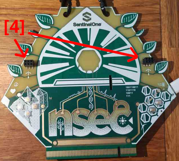
Here are pictures of the front of the badge
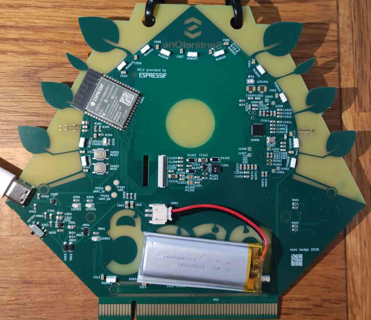
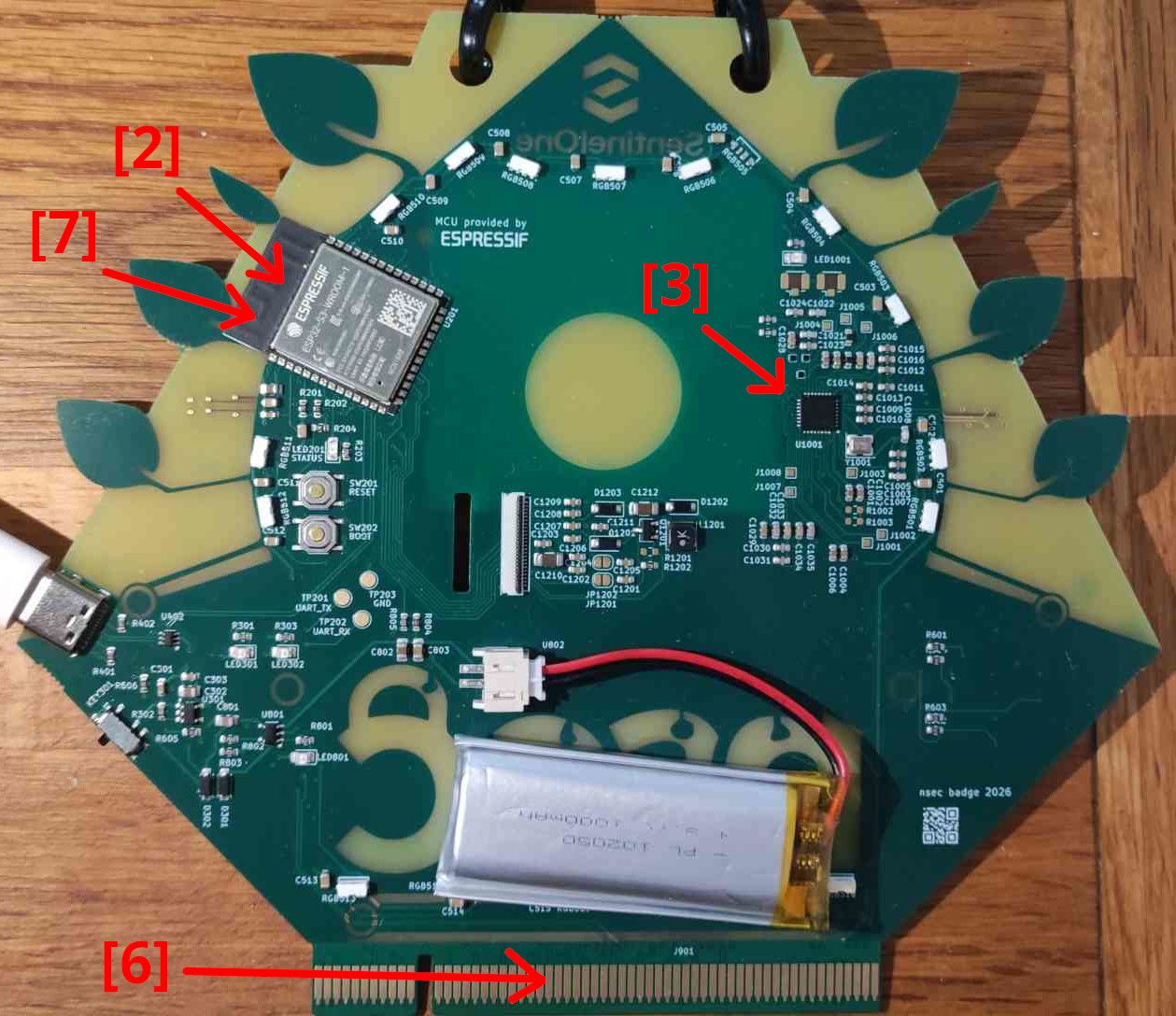
and the back:
How to connect to the badge? 101 tutorial
The badge is the same for both the conference days and the competition. To avoid giving any advantage to participants attending the conference, you will need to flash your badge at the admin tables at the start of the competition. Or you can download the source code once it is released as open source.
Once you’ve done that, you will need a USB-C cable to connect to it. Plug it into your computer and turn on the badge using the small black switch near the USB-C port.
I’ve tried using Windows in previous years, but it never worked for me, so I set up Arch Linux instead.
Once connected, you need to do:
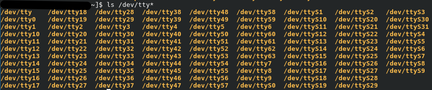
ls /dev/tty*
According to the internet, “tty” stands for “teletypewriter.” This command will display a lot of information:
When you turn on the badge, you should see one additional entry:
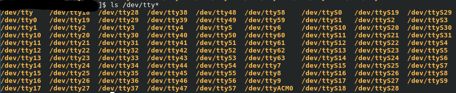
From past experience, you will typically see either ttyACM (Abstract Control Model) or ttyUSB followed by a number. I’m not sure what the other entries represent.
On a side note, every time I upgrade Arch, something seems to break and I have to manually reinstall a few things. If the device is detected but doesn’t show up properly, this is my go-to command:
sudo pacman -Syu linux linux-headers
Then you can simply connect to the badge with screen, although many other terminal emulators exist:
sudo screen /dev/ttyACM0
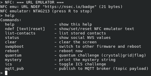
You're in! You can run help, which will usually show a list of available commands. Also, sometimes the first few characters or sentences don’t print correctly for some reason, so I just rerun the command until it works.
Quantum track
Name of the track during the CTF: The Crystal and the Grid - Part I: The Quantum Hum
Challenge designer: padraignix
When doing the quantum command, this is what you should see:
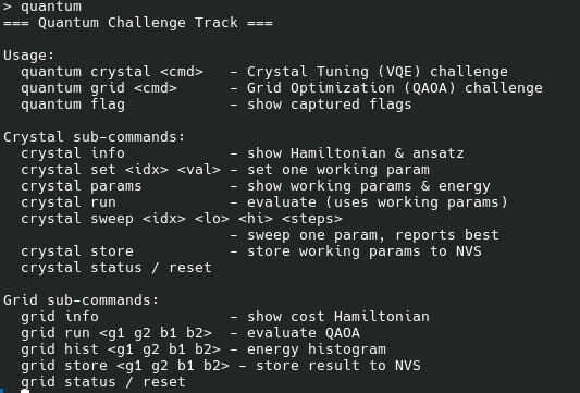
You have two challenges: a crystal one and a grid one.
Crystal
Let's do crystal info
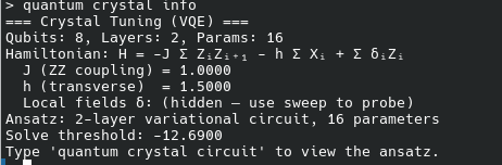
I have absolutely no knowledge of quantum, and it was giving me bad flashbacks to math classes. As the command suggests, let's try crystal circuit
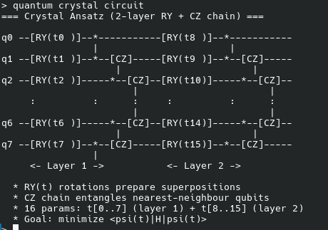
This doesn't help! After Googling "quantum for dummies" and "quantum VQE", I learned that a qubit is something that is not 1 or 0, but something in between, or a kind of probability. You can have multiple qubits that you can combine with "gates", where things rotate or transform or both, I think... And that creates a quantum circuit! I found a website where you can build your circuit but 1) I'm so fucking lost 2) It feels like the command didn't print the whole circuit? Am I supposed to guess it?
VQE stand for Variational Quantum Eigensolver, and uhm, you have energy in your circuit and I think there is a formula and I think you can calculate stuff to get the lowest "energy" state in the circuit.
This is what you'll get with crystal params
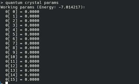
By default, all the parameters are set to 0. You can see your current energy, here -7.014217. The first command gave us the solve threshold, -12.6900, nice. I believe each badge had its own configuration, so my solving parameters won’t work for you. Legend says someone reached the threshold with all parameters set to 0.
So let's modify things a bit using crystal set {parameter number} {value you want to assign to the parameter}. This will return the updated parameter value and the new energy of the circuit

We can see the energy has decreased!
By trial and error (and 6 fucking hours of trying), I’ve learned that the parameters don’t seem to be “linked” to each other. You can modify one, find the lowest energy you can get, then modify the second one, find its lowest energy, and so on. At first, I thought parameters could only be 1 or 0, but that's not the case. They can be negative and have precision up to 10^{-4} (or 0.0001), so brute-forcing isn't really the way to go. I tried writing an algorithm to do it manually, but I was struggling to read the energy output from the badge due to printing issues (and general skill issues), so I ended up manually adjusting the parameters until 3AM saturday night
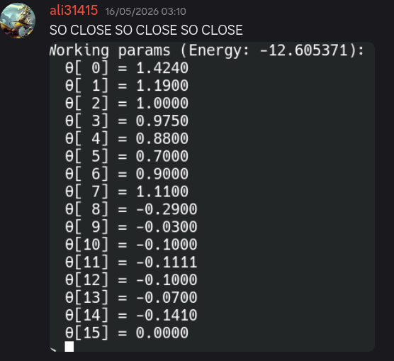
It took me a few more hours to get the right parameters. Sometimes modifying one slightly would make the energy drop significantly, while other times it would take changes to 5parameters just to reduce the energy by 0.01. Then, going back to one of them would suddenly have a much larger impact after adjusting the others. It was a long process. What eventually worked for me:
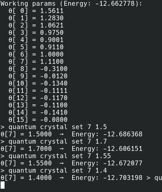
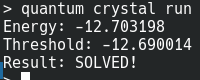
You had to run crystal store to save the parameters so they don't get obliterated. Then go to the admin table, plug your badge to their PCI thing. If the badge flashed green, it meant you had solved it, and it would write the flag to the badge, which you could then retrieve withquantum flag


Grid
Let's run the grid commands and gather as much information as possible:
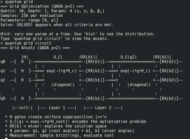
I have already solved it, hence the "SOLVED!" message. This is basically the same challenge, but with 4parameters that you adjust all at once. You can check with grid hist and gris run
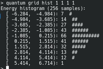
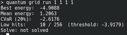
I'm not sure how to read it, but out of 256 samples, 66 have high energy. The goal is to globally have low energy. I mainly used grid run and change one parameter at a time. I got very lucky and got in within 10minutes of trying random things. What worked for me:
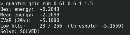
Then it's the same process: you store it with quantum store, sprint to the admin table, plug your badge to their PCI thing, pray it turns green even though you know you solved it, be happy it turned green, sprint back to your table to retrieve the flag with quantum flag and submit it.


Mystery track
Name of the track during the CTF: The Crystal (badge) mysteries, no challenge designers were specified but I talked a lot with the very cool Patrick Downing who QAed the track, and the person who actually created the track, @vicious on the NorthSec Discord. Both were very very cool and very patient with us lol
Flag 1
The challenge description contained a fill-in-the-blanks text, where the combination of the missing words formed the flag. I don't have the full text, just the beginning to give you an idea:
__   __ __  __ an advanced communication devices for __  __  __ __   __ __  __  __
__ __ __   __  __  particularly useful
for community building in off-the-grid conditions.
_  ___ __ __ __ __ with the architecture
provenance remaining uncertain, but it clearly contains traces of the
__ [1] platform, which is usually associated with programming using
sketches,  __ __  __ __  __
__ __ __ __  __.__  __ __  _ _ __  __ is built
around the ____2_3 [2] chip as the core component, while the ST2__ [3]
provides a special extension for near field communications.
[...]
___ ___ _____ ___ ___ _____ ___________ __ ___ __ ___________, _____ ___________ ___ ___________ __ _______ ____ ________ ________ ____________
(___) _____ ___ functionality is ensured through the extension port located
on the bottom side of the device. The edge connector serves multiple purposes
such as ___ ____ ____ _____ ___ (___) ____ __ ___ and crystal tuning. But it
is especially useful for debugging, for which the transmit port is mapped to
Address B23 and the receive port to Address ___ [6].
arduinoa sketch is the name Arduino uses for a programesp32s3you can read it on the chip, it's the big chrome oneST25r3916it's the only other thing that looks like a chip. If you Google ST2 NFC (Near Field Communications), you will see what it's supposed to look like. To get the number you needed 10/10 vision, or a good phone camera, to read it directly from the chipSAOstands for Shitty Add-Ons, not really a industry-standard term, the text was referring to two connectors on the badgeesptooltool to communicate with Espressif chips, the text was talking about a tool to communicate with the main chipB24this was the hardest to find, as we struggled to find the right documentation. As I'm writing this, I cannot find it again lol. This refers to the PCI connector at the bottom of the badge. A and B refer to each side of the connector, and the gold contacts are called pins. Each pin can be mapped to an address. In the documentation we found, B23 and B24 were labeled together as input and output pins, essentially acting as transmit and receive.16the text was referring to the size of the chip, to find it you can use esptool with the commandflash-id: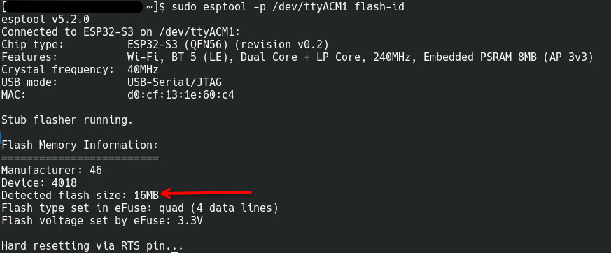
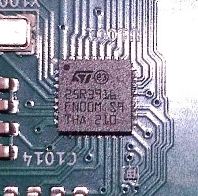
Here is also a hIgH rEsOluTioN picture of the ST2 chip where you could see the number, "ST" is the logo-ish thing and the number starts with the 2 of the "ST2"

Flag 2
Submitting flag 1 would prompt Did someone forget to remove the flag from the source
code?
Dumping the firmware using esptool:
sudo esptool.py --chip esp32-s3 --port /dev/ttyACM0 -b 115200 read_flash 0x0 0x1000000 badge_ctf.bin
-b is for the baud rate, 115200 is the standard baud rate. I believe 0x0 is the starting address where the read begins, and 0x1000000 is the end address. The dump will be stored in a file named badge_ctf.bin
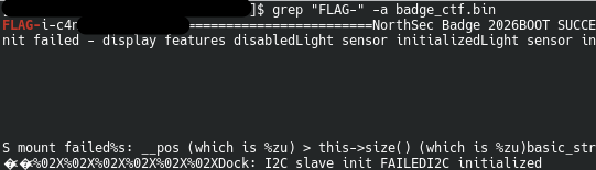
You can then simply run a grep on it! The -a flag indicates the file is binary. You can also add -i to make the search case-insensitive, so you don't grep on flag not capitalized and not find with flag for most of the CTF like I did

Flag 3
During the CTF, we discovered this very cool tool, a user-friendly interface for browsing the badge’s files, thelastoutpostworkshop.
This requires a Chromium-based browser to work, and you need to launch it with sudo (sudo chromium --no-sandbox. Otherwise, it will only say the port is busy instead of indicating that access is denied), plug in, turn on your badge and click connect!
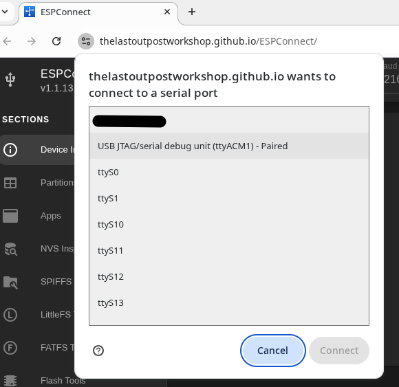
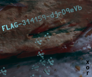
You can poke around and see some things we're seen previously. When you go to the SPIFFS tab, which stands for Serial Peripheral Interface Flash File System. You will find multiple JSON files and 2other files, pie1 and pie2, you can download them, this is pie1:

Flag 4
When submitting the last flag this message was posted on the forum:
Mmmmm… pies… I want another one!
So surely this has something to do this the other pie file, which is just data:

We unfortunately didn't get this one during the CTF, based on the other pie image with the vertical xor we tried XORing it in every vertical possible ways, With hints from Patrick when we way off track, we figured out we needed to use the bits ON the badge itself, the silly 0s and 1s:
100110011
1101110
10011
111
Even after the CTF, I was still having skill issues, so I asked my good friend (and coolest friend), Mr.Un1k0d3r. It turns out I really was having a skill issue, and the key works fine if you write a script for it. I also found this online tool that, for some reason, only works if the key is in hex:
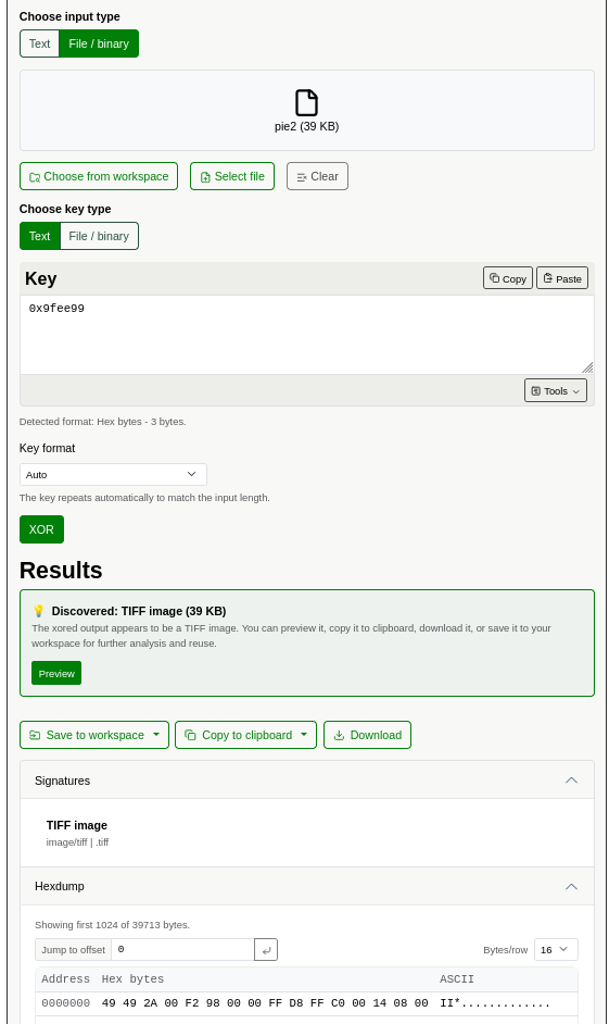
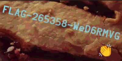
You can download the file and pray this new website doesn't give you malware as well, and you'll get a TIFF image with the flag on it:
Flag 5
You could find this flag by reversing the firmware, or, the cool way, by sniffing UART communication. When running the command mystery you would see:

As big noobs, it took us a lot of explaining to understand what we were supposed to do. The "seven even" hint refers to the UART communication protocol. In UART, each data frame contains between 5 and 9 bits, along with a start bit and an end bit. There is also a parity bit. “Seven even” indicates how we should interpret the data we see when sniffing UART communication, I think.
I don't have a picture of our pretty setup, so here is a reconstruction:
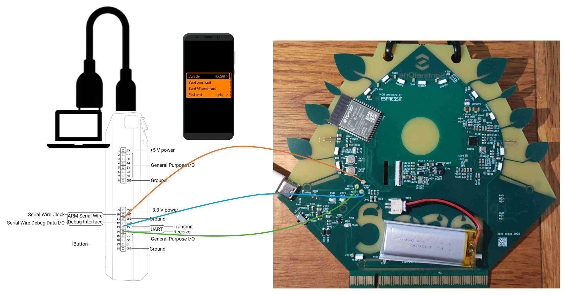
On the badge, the pins were gracefully labeled GND for Ground, UART_TX for UART Transmitter and UART_RX for UART Receiver. We kindly asked the solvering village for three small wires, which we soldered to the badge and connected to a Flipper Zero, as mapped in the image, UART_TX on the Flipper's RX and UART_RX on the Flipper's TX.
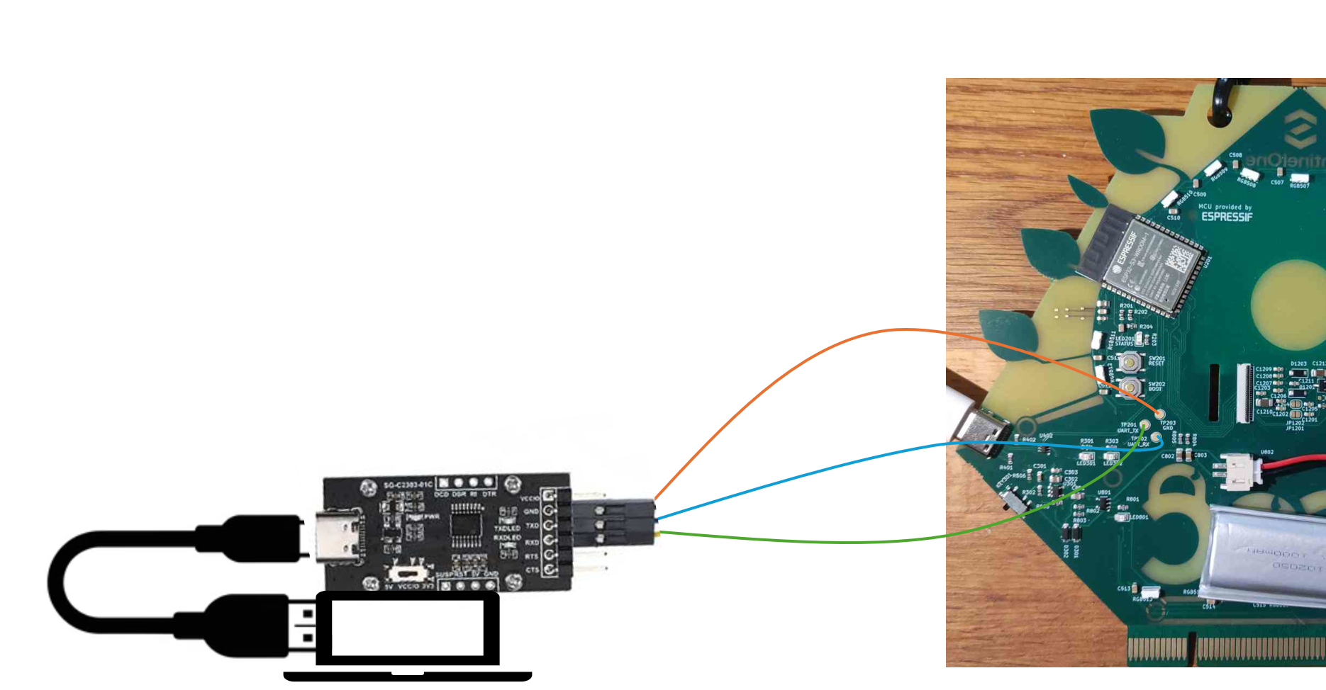
The lastest Flipper's firmware update has a UART inferface. We set up a phone to monitor what was being transmitted and adjusted the baud rate to find the right one, even if none of them would produce readable output. We also tried using a computer, but in the end we thought it might a Flipper limitation. The challenge designer very kindly lent us a serial connector with small grabbers for the wires. We didn't take a picture, so here is another reconstruction:
All of this was done to capture a dump of what was being sent. These are the parameters we used to connect:
sudo picocom --databits 7 --parity e /dev/ttyUSB0
But I'm not sure we read it the right way. You could also see what was being sent by going the reverse route:
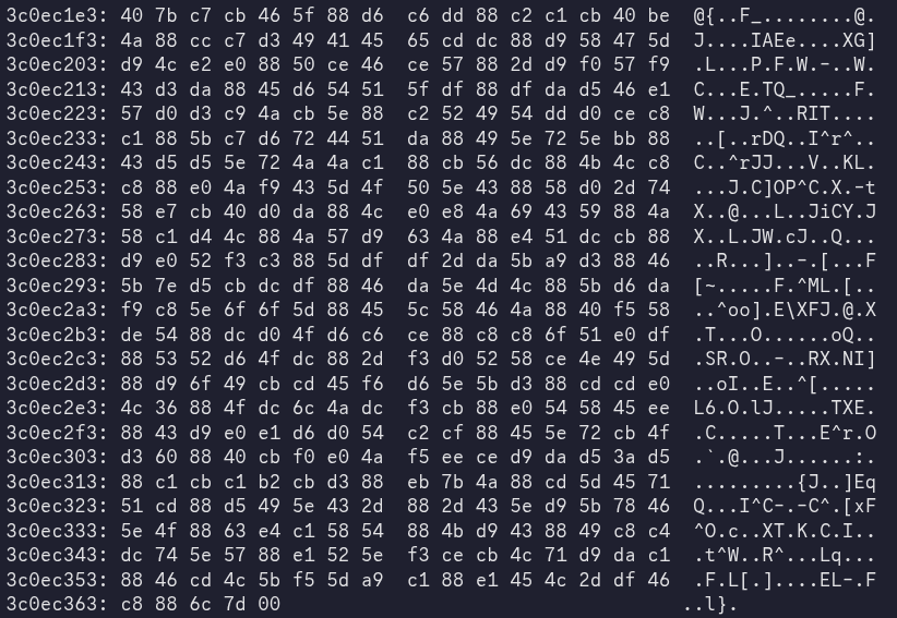
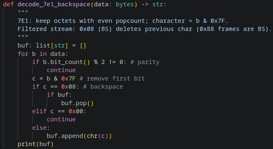
Then you can filter it, bear with me: 1. Take the bytes from the dump 2. For each byte, check whether it contains an even or odd number of 1s 3. If the parity is even, keep the byte, but ignore the first bit (the parity bit) 4. Some bytes will be backspaces, you need to handle those properly by deleting the previously kept byte
Here is the script the Cursor wrote (and for transparency, Cursor found this flag):

Bonus flag?..
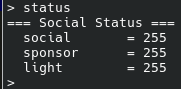
Sadly, there was no bonus flag for statmaxxing
Plant Watering ICS
This is the last track of the badge, the challenge designer is Hugo Genesse (hgenesse). There are three flags, only the first one could be obtained solely with the badge, the other two required the physical set up present in person during the CTF. We did not complete this track. Maybe next year we'll 100% the badge ;)